
Radiological Anatomy — MCQs

On this page
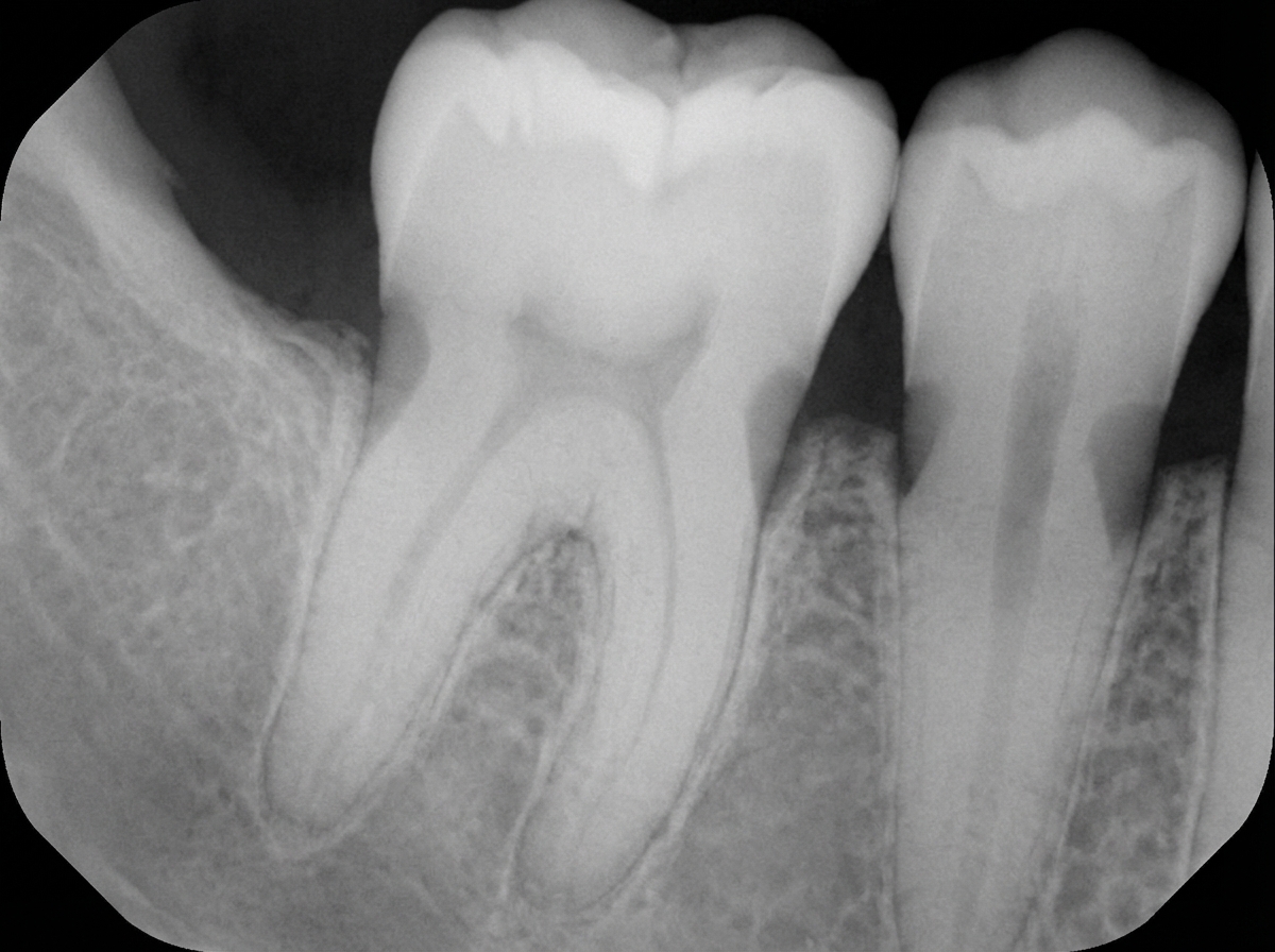
What is the likely diagnosis of the X -ray below ?
Which of the following statements is FALSE regarding the phenomenon illustrated below?
Which CT view best demonstrates paranasal sinus polyps?
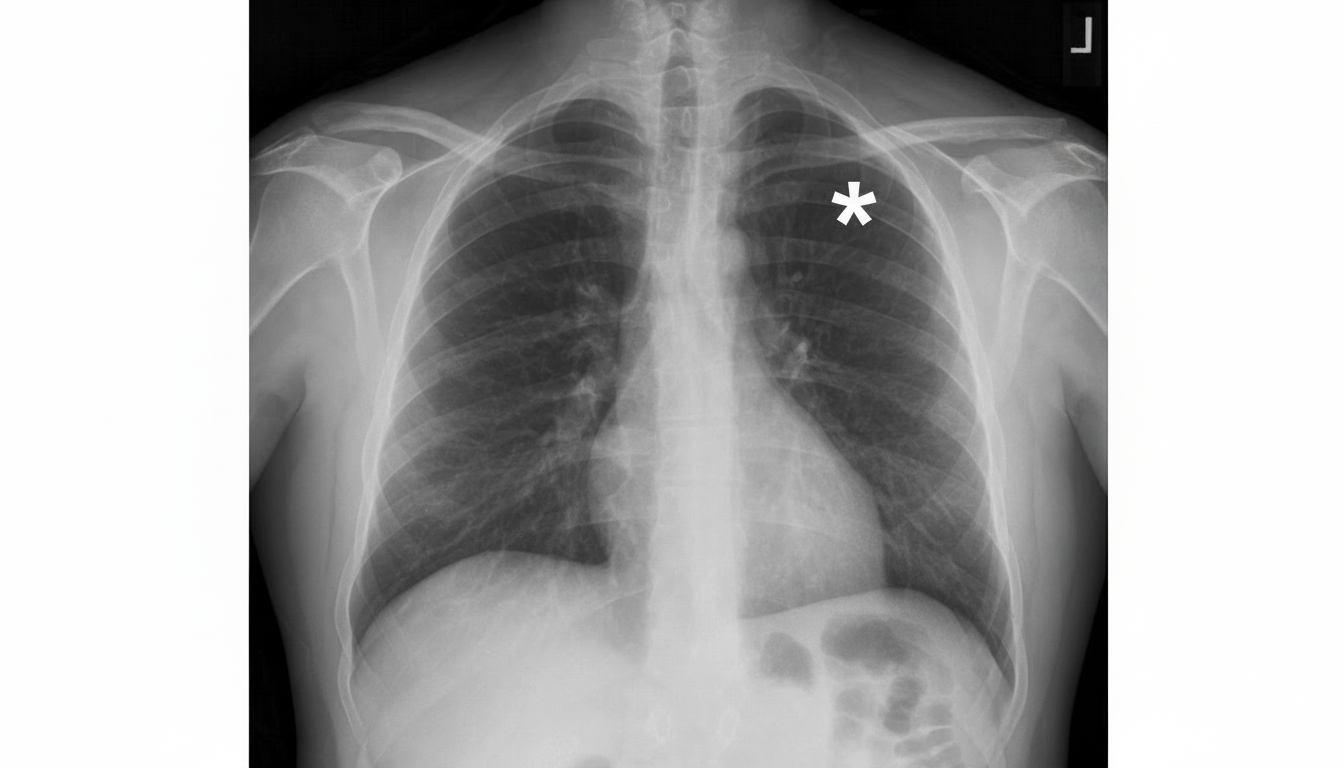
The asterisk is denoting towards which of the following structures?
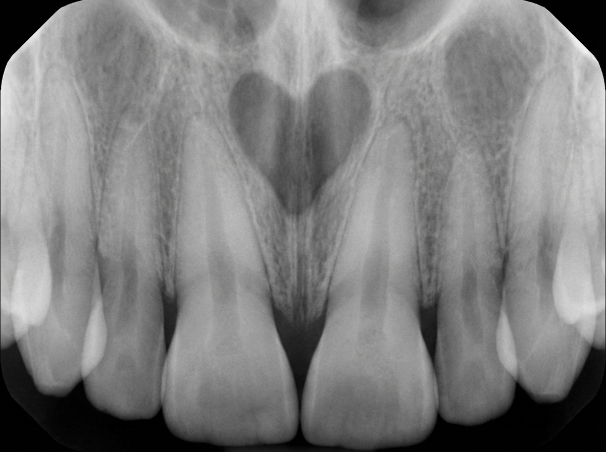
A 44-year-old male presents with a swelling on the palate. On intraoral examination, a marked swelling is seen in the region of the palatine papilla, situated mesial to the roots of teeth 11 & 21. These teeth respond normally to vitality tests. An IOPA radiograph is provided. What is the most probable diagnosis?
The feathery appearance seen in jejunal radiographs is due to:
On barium swallow, posterior indentation is seen due to:
On a chest X-ray in PA view, which of the following is NOT typically seen on the right side of the cardiac shadow?
Submentovertex projection is useful in viewing which of the following?
A radiolucency associated with a completely formed, unerupted tooth is due to what?
Practice by Chapter
Radiographic Anatomy of Skull and Face
Practice Questions
Radiographic Anatomy of Spine
Practice Questions
Radiographic Anatomy of Chest
Practice Questions
Radiographic Anatomy of Abdomen
Practice Questions
Radiographic Anatomy of Extremities
Practice Questions
Cross-sectional Anatomy: Brain and Head
Practice Questions
Cross-sectional Anatomy: Neck
Practice Questions
Cross-sectional Anatomy: Thorax
Practice Questions
Cross-sectional Anatomy: Abdomen and Pelvis
Practice Questions
Vascular Anatomy
Practice Questions
Developmental Anatomy Variations
Practice Questions
Anatomic Landmarks for Interventional Procedures
Practice Questions
Want unlimited practice?
Get full access to all questions, explanations, and performance tracking.
Scan to download app